
The Parallel Port I/O address assignment
Three addresses are available to the Parallel Ports and at boot-up, the setup routines in the BIOS ROM look for Parallel Ports on the I/O bus, and assigns the LPT numbers, from LPT 1, in this order :-
Officially LPT1 uses I/O address 0378 to 037A but when the BIOS setup routine is looking for Parallel Ports it assigns the first one it finds (in the order given above) as LPT1. The address 03BC to 03BE was first provided by a Parallel Port on IBMs Mono Display Adaptor Video Card but today it is quite common to find this address available on Parallel Port hardware.
The Parallel Ports are assigned an IRQ line as follows.
In the eight bit PC computer (PC or PC/XT type) IRQ 7 was assigned to both LPT 1 and LPT 2 but in later generation hardware IRQ 5 is assigned to LPT 2.Port IRQ LPT 1 IRQ 7 LPT 2 IRQ 7 or IRQ 5
The IRQ line is not usually used by software communicating with the LPT Ports and so IRQ 7 and IRQ 5 is usually available for other I/O functions. This means IRQ 7 and IRQ5 can be used for some other I/O function. Sound Cards as a rule use either IRQ5, 7 or 10 as the default IRQ.
Parallel Ports can be used for:
The Parallel Port Standard is based on the Centronics Parallel Interface Standard but it has been modified to be bidirectional. Some older Parallel Port hardware in some DOS type computers are not fully bidirectional and these will not work some devices such as Pocket Hard Drives and Tape Backup Drives. The standard Parallel Cable has a DB25P (plug) on the computer end (a socket is used on the computer) and a 36 pin Centronics plug on the printer end. The cable should be shielded and should be no longer than 3 metre. When ASICS chips were first used to provide the Parallel Port, some of these had trouble driving long cables (over 3 m) because they had LSI outputs rather than TTL outputs and they did not like high capacitance loading.
By 1994 this development was getting out of hand, and so the IEEE set down standard modes of operation for the Parallel Port, in an document with the title IEEE 1284-1994, Standard Signaling Method for a Bi-directional Parallel Interface for Personal Computers. Before this time there were no set standards as to how the Parallel Port should behave when connected to devices such as Printers, Scanners External Disk Drives etc. The IEEE defined five modes of operation. These modes take care of the various types of hardware that have developed over the years since the PC Computer was released.
This IEEE specification is aimed at standardising the behavour between a PC Computer and an attached device. Although the specification deals mainly with Printers, devices like SCSI Adaptors, CDROM, High Capacity Disk Drive and Tape Backup Adaptors, Optical Scanners and simple LAN interfaces are also covered to some extent.
The Unidirectional (4 bit) Port was capable of data transfer rates of 40 to 60 KB/s in the reverse direction and up to 140 KB/s in the forward direction.
The Bi-directional Parallel Port opened up the way for eight bit communications between the computer and peripheral devices across the Parallel I/O Port. This was done by redefining some unused pins in the Parallel (Centronics) connector, and by defining a Status Bit, used to indicate which direction data was traveling across the interface.
The IEEE incorporated the EPP standard into its document 1284-1994 but because some minor changes they made to the 1992 version of the standard, we now have two incompatible standards for EPP. There is the original EPP Standards Committee version 1.7, and the IEEE 1284 version. Because the differences were only minor, new peripherals can be designed to cope with the two variations, but older peripherals made to the original EPP 1.7 standard may not work with the newer IEEE 1284 ports.
Another feature of ECP is a real time data compression. It uses Run Length Encoding (RLE) to achieve data compression ratio's up to 64:1. This comes is useful with devices such as Optical Scanners and Printers where a good part of the data is long strings which are repetitive.
The Extended Capabilities Port supports a method of channel addressing. This is not intended to be used to daisy chain devices but rather to address multiple devices within one device. Such an example is some of the latest Fax machines on the market. They can be connected to a computer via a Parallel Port and can operate as separate devices such as the Scanner, Modem/Fax and Printer, where each part can be addresses separately, even if the other devices cannot accept data due to full buffers.
As originally designed, the Control lines were used as Interface Control and Flow Control (handshaking) signals from the PC to the printer. The Status lines were used for Flow Control signals and as Status Indicators for such things as paper empty, busy indication and interface or peripheral errors. The data lines were used to provide data from the PC to the printer, in that direction only. As we have already said, later implementations of the Parallel Port allowed for data to be driven from the peripheral to the PC.
The original Parallel Interface Port used open collector TTL devices on each side of the interface and these can be damaged by ESD.
The Parallel Ports in modern PC hardware use V.L.S.I. devices that are not open collector devices and these are also easy to damage by ESD. These outputs often do not conform to the TTL standards, and they may have trouble driving older printers, long cables, and external signal-powered devices.
| Line name | DB25S | 36 pin Centronics | Notes |
|---|---|---|---|
| Strobe | 1 | 1 | a 1 usec pulse used to clock data into the printer |
| Data 0 | 2 | 2 | |
| Data 1 | 3 | 3 | |
| Data 2 | 4 | 4 | |
| Data 3 | 5 | 5 | |
| Data 4 | 6 | 6 | |
| Data 5 | 7 | 7 | |
| Data 6 | 8 | 8 | |
| Data 7 | 9 | 9 | |
| Acknowledge | 10 | 10 | acknowledge signal from printer to computer |
| Busy | 11 | 11 | used by the printer to stop the flow of data |
| Paper Empty | 12 | 12 | indicates the printer has run out of paper |
| Select Out | 13 | 13 | indicates the printer is "on line" |
| Auto Feed | 14 | 14 | not often implemented - wired to ground |
| Error | 15 | 32 | indicates a fault in the printer (motor jammed etc) |
| Initialisation | 16 | 31 | clears the printers buffers and resets defaults |
| Select input | 17 | 36 | a signal on this line is the same as "select button" |
| Ground | 20 to 25 | 18 to 25, 16, 19 to 30, 33 | 18 to 25 are paired with the Data wires pins 2 to 9 as shields |
Note - the original specification included plus 5 volt on pin 18 and a "clock signal" from pin 15.
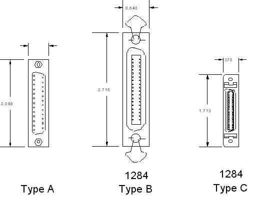
The IEEE 1284 standard specifies 3 different connectors for use with the Parallel Port. The first one (1284 Type A) is the DB25 connector found on the back of most computers, and the second is the (1284 Type B) 36 pin Centronics Connector found on most printers. The third, the IEEE 1284 Type C connector, is also a 36 conductor connector like the Centronics, but it is much smaller. IEEE 1284 Type C also defines two more pins for signals which can be used to see whether the other device connected via it, has power applied.
| Back to the PC and its I/O Ports | Back to the opening index | Book two index |
| The common I/O port assignments | The PCs Serial (Comms) ports | The Games (Joystick) port |