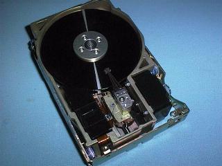
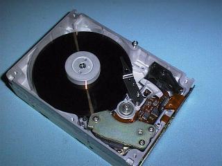

A Hard Drive consists of a sealed enclosure inside of which there are one or more rigid platters that are coated with magnetically sensitised material. The platters are rotated at a constant speed and data can be written to, and read from the surface of the platters, by means of electromagnetic read/write heads. A circuit board is attached to the outside of the Hard Drive assembly to provide the Electronics needed to control and interface the drive to the PC. Several interface technologies are available for use with PC hardware and the types af cables depend on the interface in use. You will learn more about this soon.
The major parts inside a Hard Disk assembly include
Platters: Most platters or disks are made of an aluminum alloy, but ceramic or glass platters have also been used. The diameter of the Platters in Inches can be 21/2, 31/2 or 51/4, and the thickness of the media can be from less than 1mm to about 3mm. The platters are coated on both sides wit a magnetic material. Older drives used a ferrite compound applied by squirting a solution onto the surface and rotating the platter at high speeds to distribute the material by centrifugal force. This process left a rust colored ferrite layer which was then hardened, polished and coated with a lubricant. Newer drives apply the magnetic layer by plating a thin metal film onto the surface through galvanization or sputtering. These surfaces have a shiny chrome-like appearance.
Spindle Motors: Most drives have several platters that are separated by disk spacers and clamped to a rotating spindle that turns the platters in unison. A direct drive, brushless spindle motor is built into the spindle or mounted directly below it. (Sometimes this motor is visible from outside of the sealed enclosure.) The spindle, and consequently the platters, are rotated at a constant speed. The first drives rotated at 3,600 RPM but over the years this speed has increased to 4800, 5400, 7,200 and now as fast as 10,000 RPM. In contrast, Floppy Disk Drives spin floppy disks at 300 or 360 RPM. The spindle motor receives control signals through a closed loop feedback system that stabilizes to a constant rotation speed. The control signals come from information written onto the platters during manufacture or with older drives, from physical sensors.
Read/Write Heads: Both sides of each platter are coated to provide separate magnetic surfaces, and so there is one electromagnetic read/write head for each side of each platter. A drive with 4 platters would have 8 sides and 8 heads. Some drives use one side as a dedicated surface for control signals leaving an odd number (5,7,etc.) of heads for actual use. Each head is mounted onto the end of an access arm and these arms are moved in unison under the control of a single actuator mechanism. The spinning disk(s) create an air cushion over which the heads float. Depending on design, this air buffer ranges from 2 to 15 microns. By contrast, a smoke particle or finger print is about 30 microns in size!
The heads are not supposed to come into contact with the surface during rotation. Only when powered off should the heads come to rest on the surface, but this should be over a specific area of the surface, reserved for that purpose. Most drives built since the late 1980's employ an automatic parking feature which moves the heads to this designated region and may even lock the heads there until powered up.
Head Actuators:
|
|
The head actuator is the positioning mechanism used to move the arms and consequently the heads, back and forth over the surface. The first Hard drives used a Stepper Motor to position the heads. The stepper motor rotated in either direction by reacting to stepper pulses, and it moved the head assembly back and forth by means of a "rack and pinion" or by a band attached to the actuator arms. This design, still used for floppy drives, is not suitable for current Hard Drive track densities. The access speed of stepper motor drives was between 30 and 70 mSec.
For a long time now a Voice Coil actuator has been used to control the movement of the heads. A coil,attached to the head assemly, moves toward or away from a permanent magnet, controlled by the amount of current flowing through the coil. This is an analog system, with the exact amount of movement controlled by the exact amount of current applied. The actual position of the coil is determined by servo (or indexing)information, which is written to the drive by the manufacturer. The location of the heads over the tracks on the platters is adjusted to different tracks by reading and reacting to this information. The access speed of voice coil drives is between 10 and 20 mSec.
Preamplifier circuitry: From inside the sealed assembly, there are electrical and control wires for the spindle and head actuator motors, and from the heads themselves. The flex cable from the heads usually has a preamplifier chip built in, inside the sealed assembly. This chip takes pulses from the heads (as close to the source as possible) and cleans up and amplifies these signals before transmission to the electronics outside of the housing.
Air Filtering and Ventilation: Minor wear of internal components and occasional contact of the heads with the surface can cause microscopic particles to be loosened within the HDA. A permanent air filter is mounted within the air stream to remove these particles before they can cause damage to delicate mechanisms. Most drives also have a small vent to allow for minor air exchange from outside of the housing. This allows for equalization of air pressure so drives can be used in different environments without risk of imploding or exploding.
The capacity of a Hard Disk Drive can be increased by having more Tracks per platter (Cylinders), more Sides (Platters) and/or more Sectors per Track. The capacity can also be increased by having more Sectors on the outer tracks than on the inner tracks, a technique known as Constant Linear Velocity recording .
For quite some time the maximum number of tracks that could be accommodated was 1024 and so Hard Disk Drives were built with more and more Heads, and as many as 16 Heads on eight Platters. Todays Hard Disk Drives have far more Tracks, and only a few Heads. It is expensive to make the head assemblies so the fewer heads there are the cheaper the drive. Track densities of greater than 4000 Tracks per inch are used on todays high capacity Hard Disk Drives. This means a typical 1.2 GByte drive had 3900 Tracks (Cylinders) across the surface of a 3.5 inch Platter. The Conner CFS1081A one GByte Hard Disk Drive had 3924 tracks, two Platters and four Heads and from 90 to 170 Sectors per track.
The number of sectors per track has risen from 17 on the first Hard Disk Drives to as many as 170 today. To increase the capacity, the number of sectors per track is no longer constant with more sectors on the outer tracks where the length of the track is greatest, and fewer sectors on the inner tracks.
A Floppy Disk format is a single stage process that is carried out using the DOS FORMAT command.
With older Hard Disk Drives you had to perform the low level format yourself but modern drives are supplied with the low level format in place. This means the process of formatting a Hard Disk Drive is now only a two stage process. These stages are:
1. Low Level Format
This process sets up the cylinder, side and sector data on the platters. It defines the cylinders, sides and sectors.
The 8 bit PC/XT type computer used an 8 bit Hard Disk Drive Interface and processes involved in performing a low level format on this type of computer is usually different to that required when performing a low level format on a AT computer. The most common Hard Disk Dive Interface used in XT type computers used the ST506 interface and ST506 Drives were not supplied with the low level format pre-formed. This was because the various brands of controller card did not use the Hard Disk Drive in the same way, and a drive could not be changed from one Interface card to another, without performing a low level format again.
The original IBM PC/XT required a low level format program that was supplied on the IBM PC diagnostic disk. Most ST506 interface cards from other manufacturers had a low level format routine built into the BIOS extension ROM on the card. This ROM is required on an PC/XT Hard Disk Drive Interface card to supply BIOS support for the Hard Disk Drive. The BIOS ROM in the PC/XT type computer does not have support for Hard Disk Drives and this needs to be added by the BIOS Extension ROM on the Hard Disk Drive interface card. This ROM is addressed to start at C8000 (C800:000 in segment and offset). The low level format routine is accessed using debug and the G command (G for GO). The address called depends on the brand of card. Two common addresses used are :-
Older AT, and some early 386 computers used Hard Disk Drives with the ST506 interface and these required a setup disk to configure the CMOS, and to perform a low level format. The AT type computer (and all later generation PC Computers) has support for Hard Disk Drive built into the computers normal BIOS, and does not require a BIOS extension ROM on the interface card.
Modern DOS computers have the setup routines that configure the CMOS, and provide diagnostic services, built into the computers normal BIOS. You gain access to these services at power on by some Hot Key combination. The most common combination is to hit the DEL key just as the Post Routines finish.
ESDI Interfaced Hard Disk Drives provided greater capacity than ST506 drives and as they were more expensive, they were used in higher performance systems. ESDI drives were usually supplied with the low level format already performed.
Many early Hard Disk Drives suffered from a problem of self demagnetising and this lead to the eventual loss of some of the overhead data (sync pulses, and Track, Sector and Side details) that were not rewritten each time a Sector was rewritten with new data. These overheads are written by the low level format process. In critical situations where data loss was disastrous, the only way to restore the overheads was to perform a low level format on these Hard Disk Drives at about two yearly intervals. This involved backing up all the data on the Disk first, as a low level format destroys all the data on a Disk.
Since about 1987, the IDE Hard Disk Drive Interface has been the most popular DOS computer Hard Disk Drive interface. IDE Hard Drives are supplied with the low level format already performed and should not be low level formatted again. You may require a special low level format routine, supplied by the manufacturer, if the low level format becomes damaged.
IDE hard Disk Drives use RLL or ESDI encoding methods internally but because the Drive Interface is built into the Drive, the user does not need to know about this. The Hard Disk Drive configuration reported to the PC Computers CMOS setup is not the drives real configuration, the system uses translation so the parameters can be made to fit into the limits imposed by, the BIOS, the Operating System and by the Hard Disk Drive Interface.
2. Partitioning
The second process is partitioning. The DOS external command FDISK performs this process. Partitioning allows us to split a Hard Disk Drive into multiple sections. The split can be for two alterative operating systems, or to make a large Hard Disk Drive into a series of smaller drives. Originally FDISK provided for a DOS partition and a NONDOS partition that was intended to be used by another operating system.
DOS versions up to and including 3.3 could not make use of a Hard Disk Drive larger than 32 MByte without the help of a Device Driver. These older versions of DOS could only split a Hard Disk Drive into a DOS partition and a Non DOS partition. These DOS versions required a DEVICE DRIVER to make the NONDOS partition into a partition DOS could recognise. This was usually provided by a product called Drive Manager, an after market product from one of the Hard Disk Drive manufacturers. This process involved loading a DEVICE DRIVER from the CONFIG.SYS file and as this driver was a memory resident routine it sometimes caused trouble with other routines and / or applications.
MSDOS DOS 3.3 added the concept of Primary and Secondary DOS partitions to FDISK. With DOS 3.3, larger Hard Disk Drives could be split into a Primary DOS partition up to 32Mbyte and a Secondary partition. The secondary DOS partition is then split into LOGICAL drives, none of which can be larger than 32Mbyte. The primary partition is called the Physical drive and is assigned the letter C:. The secondary partition is split, if larger than 32 MByte, into Logical drives. Each Logical drive is assigned the letters D:, E: etc
MSDOS DOS version 4 introduced support for larger drives and then the size of a hard drive was limited by the BIOS, and by the Hard Drive Interface, rather than by DOS only. DOS version 4 was soon replaced as it had a number of problems.
FDISK writes a partition table on the disk so DOS can keep track of the disks partition data. The partition table is located in the very first sector on the disk - cylinder 0 , side 0 , sector 1.
Note
The partition table only occupies one sector , the rest of the sectors on cylinder zero, side one are not used. The boot strap loader uses the partition table to look for an active (bootable) partition. When splitting a Hard Disk Drive into partitions, the primary DOS partition must be made active using FDISK. If you use the automatic process provided on modern DOS master disks to install DOS, this part of the process will be done for you.
3. High Level Format
This process sets up the DOS structure for the Hard Disk Drive. It writes the boot record, creates the FAT table and the directory and tests the Disk for bad sectors. The DOS external command FORMAT is used to create the high level format.
The first Hard Disk Drive (usually C:) should be formatted with a system (Format C:/S). Any other Hard Disk Drives, or partitions, should be formatted without a system to save disk space (Format D:).
Limits imposed by the BIOS and the 16 bit FAT (File Allocation Table) used by DOS, Windows and the original Windows 95, limit the maximum size of a Hard Drive partition to 2100 Meg byte. The introduction of an alternative 32 bit FAT is overcoming this problem.
You can see the cluster size of a Hard Disk Drive by using the CHKDSK command from the DOS prompt, either under DOS 6.xx or under Windows 95 DOS. CHKDSK reports on the bytes in each allocation unit, this is talking about the cluster size.
| Partition size (up to) | Number of sectors per Cluster | Cluster size in bytes |
|---|---|---|
| 128 MByte | 4 sectors | 2,048 |
| 256 MByte | 8 sectors | 4,096 |
| 512 MByte | 16 sectors | 8,192 |
| 1 GByte | 32 sectors | 16,384 |
| 2 GByte | 64 sectors | 32,768 |
| Partition size (up to) | Number of sectors per Cluster | Cluster size in bytes |
|---|---|---|
| 256 MByte | 1 sectors | 512 |
| 8 GByte | 8 sectors | 4,096 |
| 16 GByte | 16 sectors | 8,192 |
| 32 GByte | 32 sectors | 16,384 |
| 2 TByte | 64 sectors | 32,768 |
Important: A hard drive formatted with a FAT32 file system will not be readable under DOS, all older versions of Windows, the original Windows 95, and versions of Windows NT less than version 5.
Two types of Original DOS Disks were available from Microsoft.
If you do not wish to use the automatic installation routine you can bail out by pressing the F3 key when prompted to do so but remember, most of the files on "original DOS disks" are compressed and can't be run from the DOS prompt. They must be uncompressed before they are installed on a Hard Disk Drive. In this case a compressed file is indicted by the last letter of the file extension being replaced with an _ (underscore). An un-compression utility is provided on disk one but this is difficult to use manually.
The external command files for FDISK, FORMAT and SYS are not compressed on disk one and can be run from the DOS prompt. This means you could partition and Format a Hard Disk Drive, and put an operating system on it only, simply from the A: prompt. Remember, all DOS requires to boot the computer are the three DOS system files, IO.SYS, MSDOS.SYS and COMMAND.COM.
Simple generic CONFIG.SYS and AUTOEXEC.BAT files are sufficient to get the computer up and running and most accessories and applications will modify these files as required. If you later create a UTIL subdirectory or a MENU subdirectory you should add these to the PATH statement. Remember the DOS environment is a finite resource and each addition to the "PATH" uses up some of this resource. Be careful to add only those subdirectories that will benefit from being on the path, to the PATH statement.
Windows 95 and Windows NT are usually installed from a CDROM and you need a Boot Disk that installs the CDROM drivers before you can start to install these modern Operating Systems. You will learn more about this proceedure in the Module, Single User Operating Systems.
| IDE, ATA, CAM, ATAPI and LBA | More technical details of EIDE | Hard Disk Drive Interfaces | Back to the opening index | Book four index |