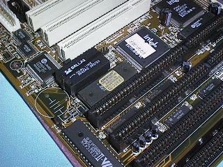
The Dallas module

Switch off the system, and unplug all the cables connected to it, both the power cable and the signal cables that go to the peripherals and make sure you note where each cable went. Slide the cover off the system's case. At this stage, and throughout the process, guard against dangerous static discharge by grounding yourself to the case chassis using a WRIST STRAP. The case should also be grounded to a good earth point. If your workbench is not equipped with a suitable earth point you could equip a three pin plug with only an earth wire and a clip on the other end to connect to the computer under repair.
Note where all the cables attached to the various expansion cards are attached, paying attention to the orientation of pin one for each cable. Disconnect cables attached to the Expansion Cards and then pull out all Expansion Cards. The Expansion Cards will have Hard and Floppy disk cables and Serial and Parallel cables.
Some PC cases allow easy access to the System Board with the board in place but if access is not that easy it is better to remove the board from the case. You may be able to gain better access if you remove the power supply. The System Board will have a speaker cable, one or more cables for the system lock, power led, turbo led, turbo switch and reset switch. If your system follows standard PC design, you'll find only one or two screws, usually one near the center of the back of the board and perhaps one near the center at the front of the board. Take out these screws and then either slide the board to the left to disengage the mounting posts or if the system uses the press fit mounting posts, squeeze each post with long nose pliers and press them out of the holes in the case.
Once the System Board is out, lay it flat on an Anti Static Bag on your work surface and connect your wrist strap to an earth pad near one of the mounting holes on the back of the board. The mounting hole near the keyboard socket usually provides an earth connection between the System Board and the computers case.
To remove your old Processor, hold the rake with its long arm angled upward, its teeth horizontal and pointing toward one side of the chip. Slide the teeth of the rake under the edge of the chip so they interleave with its pins. To do this, slide the rake parallel to the edge of the chip while pressing slightly inward until the teeth slip into place.
Now apply downward pressure to the long arm of the rake until you feel the chip give. Then lift the side of the chip, but only slightly. Trying to pry up one side all at once will bend its connecting pins; this will make the chip impossible to replace should you ever need to.
Move the rake to the opposite side of the Processor, and pry that side slightly upward. If the chip lifts easily, return the tool to the first side and pry a bit more. If the chip is reluctant, work your way around all four sides of the chip, prying each one upward in turn. In most cases, you'll need to pry each side about three times before the chip is loose enough for it to be lifted out of its socket.
If the computer has a ZIF socket, the process is far easier: Simply raise the lever at the side of the socket, and lift the old Processor free.
Once you've popped the Processor from its socket, hold the chip only by its edges. To store it, press the chip into a piece of black foam or slip it into one of the "chip carriers" Processor chips are supplied in.
Intel indicates the orientation of it's Processor chips in several ways. The most obvious is the bevel on the lower left corner of the square package. Turn the chip over, and you'll find that one of the pins has a square base and a small gold ray. These point toward the same corner of the chip.
Most CPU sockets have similar indications: a notched outside corner, a filled-in corner, or a legend or out-line silk-screened on the mother-board itself. Orient the Processor chip so that its notched corner follows the alignment indicated by the computers Processor socket.
Holding the Processor only by its edges, place the chip atop its socket in the proper orientation. With a ZIF socket, simply raise the lever; the chip should drop directly into place. Lock the lever, and your Processor is installed. With a conventional socket, you'll need to position the Processor carefully while inserting it. Make sure all the leads of the Processor match holes in the socket. Take care not to offset the chip by one or more rows in any direction.
When you're absolutely certain the Processor is properly aligned, begin to press it down into the socket. Start with firm, even pressure from your thumb or forefinger on the center of the chip. If it doesn't slide smoothly into the socket, most chips won't, work it down by pressing on each side individually, a small step at a time.
Ease the Processor down until the bottom of the chip nearly touches the top of the socket. Then inspect your work to ensure that none of the gold leads of the chip has been bent.
If any pins are bent, carefully remove the chip, and use smooth needle-nose pliers to straighten them out. Once you're sure the Processor chip is in place, put the computer back together.
If you apply power to a System Board with the Processor plugged in the worng way around, the Processor or the System Board, or both, may be destroyed.
Important - If you are replacing a DX40 or DX50 chip with a DX2/66 or DX4/100, make sure to set the clock speed back to 33MHz. You could if you are prepared for some failure try running these processors at 40 or 50MHz, a risky process known as over clocking.
Make sure the Processor has the correct operating voltage, remember some of the DX2 and DX4 chips require a lower operating voltage and the chip will be destroyed if powered up with 5 volt.
If you are replacing 486DX Processors from other manufacturers look for a different jumper configuration for these Processors than for an Intel device. Remember, boards without jumpers for the "other" 486 Processors may not work with these Processors.
You can see from this how important is to have the system documentation for the boards fitted to the computer. Many system boards will be of no use if you do not know the jumper setting for them and as this hardware is now very old, this information will not be available in most cases.
Intel produced a range of DX2 Processors under the name OverDrive and these are basically 80486DX2/66 Processors with a built in voltage regulator and a heatsink. The idea behind the OverDrive Processor is they were a direct replacement for a 80486DX chip and provided almost twice the performance. Intel produced two versions of the 80486 OverDrive Processor to accommodate a range of Processor sockets found on early 80486 System Boards. Most 80486DX Processor boards will operate with an Intel DX2 or OverDrive Processor but this is not the case with the cloned DX2 Processors.
Be careful of the System Boards that could take either 80386 or 80486 Processors. These are now quite old and many do not work reliably with even Intel OverDrive Processors. It is usually better to replace these boards with modern Local Bus System Boards, after all they have been in use for three or four years. Some of the early Upgradable System Boards even had a 80386 Processor surface mounted on the board and a series of jumpers to disable this "built in" Processor so the board could be upgraded.
As a general rule, the DX4 chips only operate reliably in recent System Boards that may have been tested with these chips during the design stages and the AMD and Cyrix chips are more of a problem than the Intel chip when it comes to upgrading systems to DX4 specifications.